Using AI to generate modern QSL Cards

With the recent explosion of artificial intelligence (AI) art generators that are making the news of late for all the wrong reasons, I decided to see if I could put it to good use and design some futuristic QSL cards.

Having recently been contacted by the Special Callsigns QSL Manager and being advised that there were 18 QSL cards waiting for me, I decided it was time to create some QSL cards of my own for future use.

Having never used any form of online AI and not having any artistic abilities I was amazed how easy it was to create images using nothing more than a paragraph or so of text to describe what it was I wanted to create.

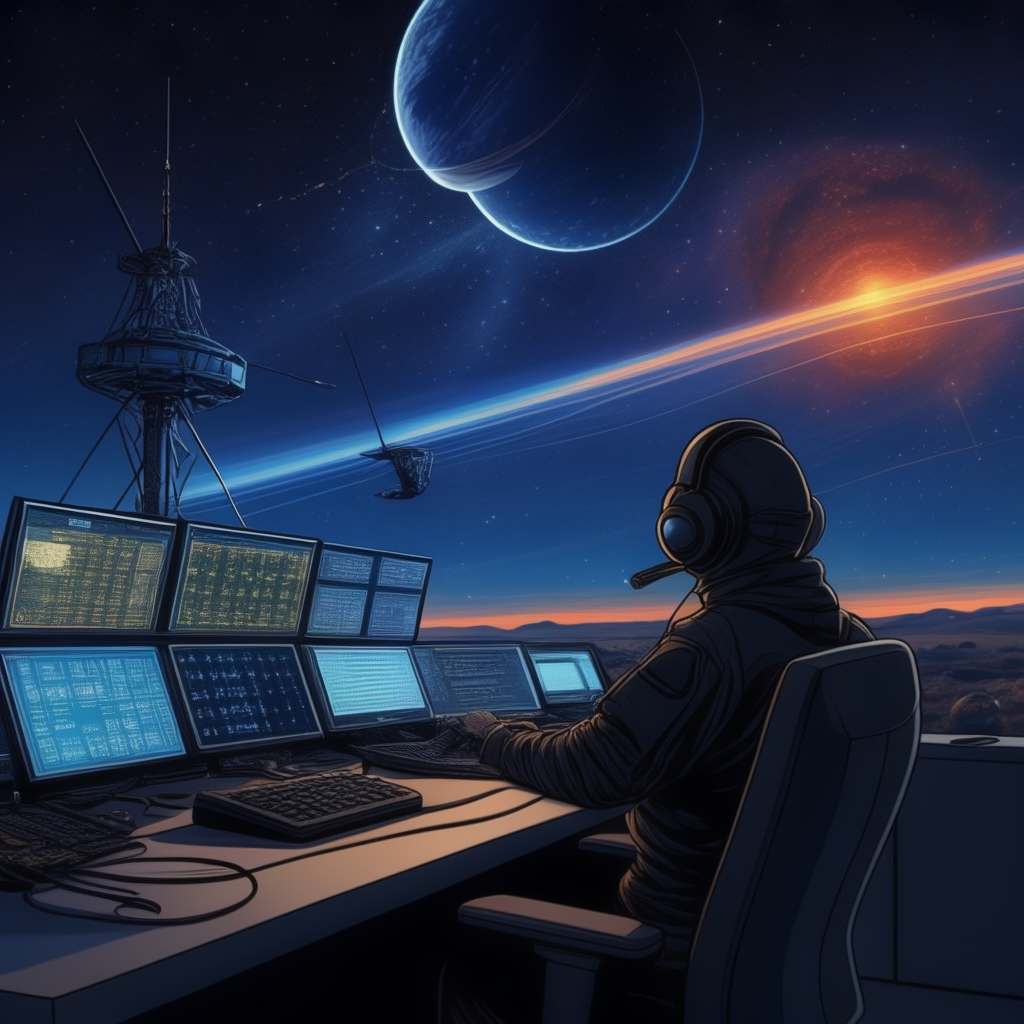
Since all the QSL cards I received were for contacts on the QO-100 satellite, I set out to create a visually futuristic QSL card that was based around a radio HAM operator and satellite communications.

M0AWS - 1st attempt to create a futuristic QSL card using AI Art
M0AWS – 1st attempt at creating a futuristic QSL card image using AI Art

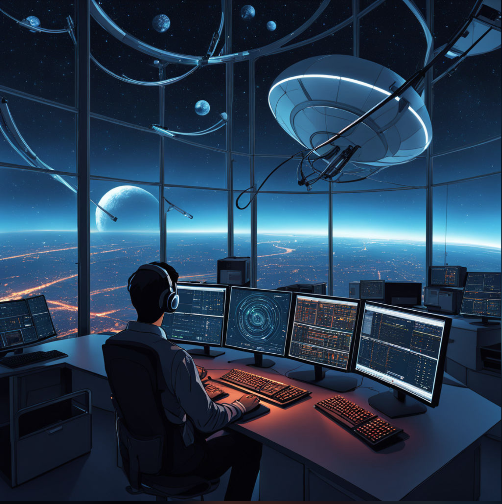
To my surprise the results of my first image generation were surprisingly good. The AI generated an image that resembled the simple text that I entered, although I never requested a one legged HAM operator!

Pleased with my very first attempt I gradually improved the description of what I was looking for, adding more and more detail to the text and including things that I wanted to see in the image. Over a fairly short period of time this approach started to generate some very interesting images.

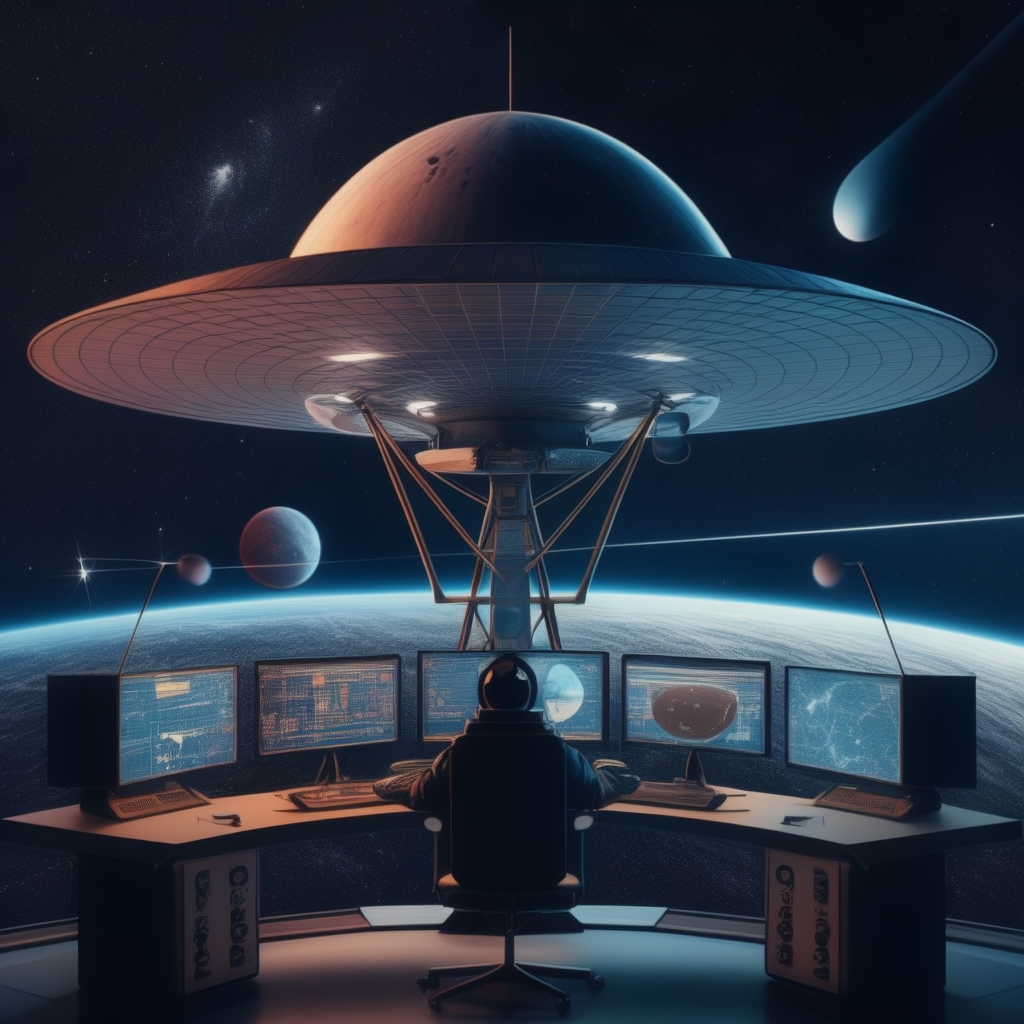
With each iteration I gradually got closer to what I was trying to achieve but, never quite got exactly what I wanted so, I decided to rewrite the descriptive text adding even more information than before. The text was now a full blown paragraph with quite specific things described including the angle at which the scene was being viewed from.

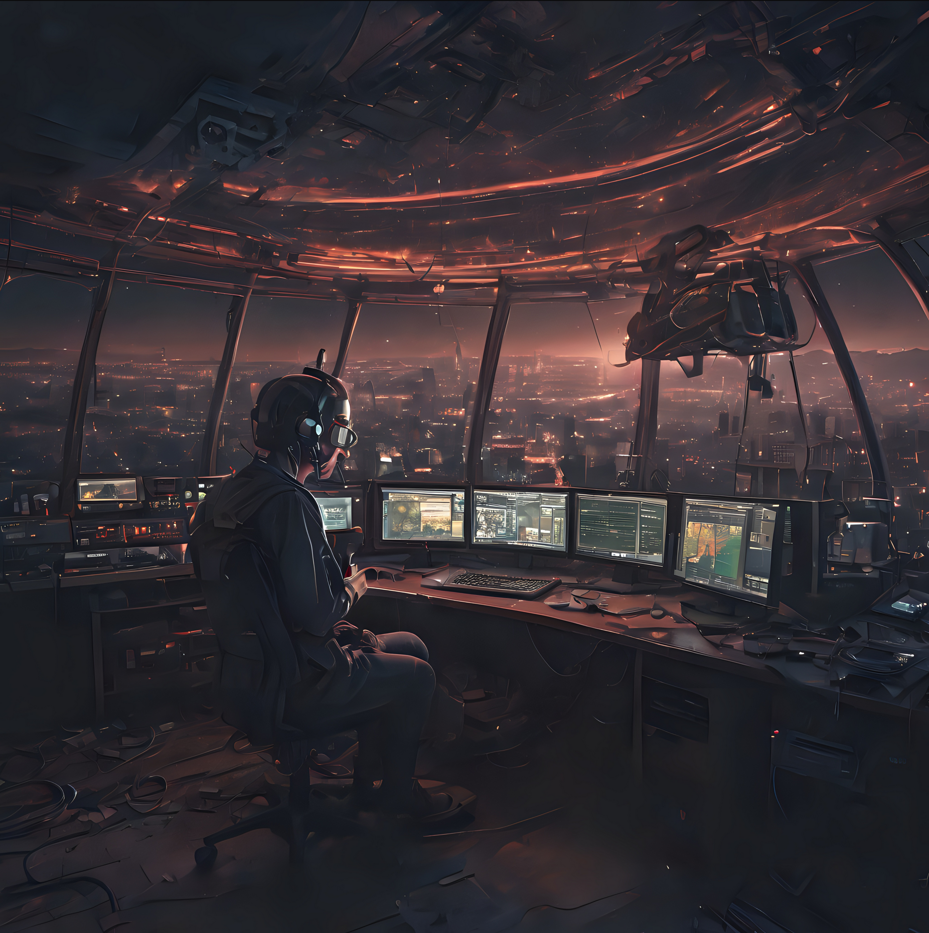
The other option I wanted to try out was the theme functionality that the AI offered. This allows you to set a theme for the image from things like steampunk, cartoon, manga, real world and many more. The results were quite impressive and added yet another angle to the image generation.

I disappeared down the theme AI Art generation rabbit hole for quite some time and generated some very interesting and fun results. The best by far though was the Thunderbirds themed image, this did put a smile on my face!

M0AWS - AI Art QSL Thunderbirds Themed
M0AWS – AI Art QSL Thunderbirds Themed

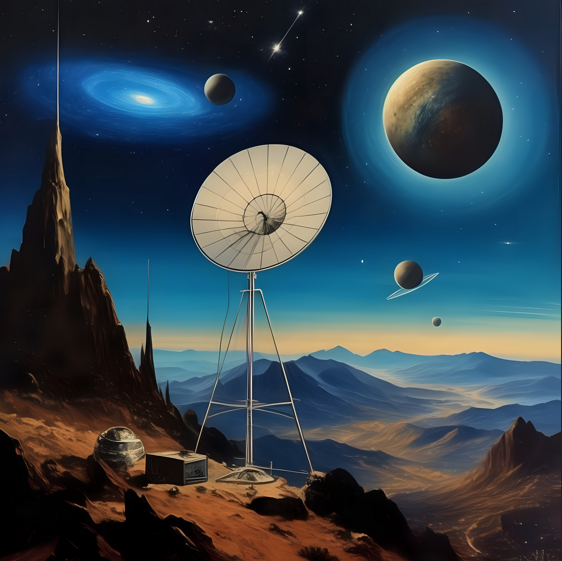
At the other end of the spectrum I tried the Salvador Dalli theme, it produced an image that was very like the work of the famous artist but, wasn’t quite what I was looking for.

M0AWS - AI Art QSL Salvador Dalli Themed
M0AWS – AI Art QSL Salvador Dalli Themed

After much fun I eventually settled on the image I was after, a futuristic scene of a radio HAM with a satellite ground station over looking a mountain range and city below.

M0AWS Satellite QSL Card generated using online AI

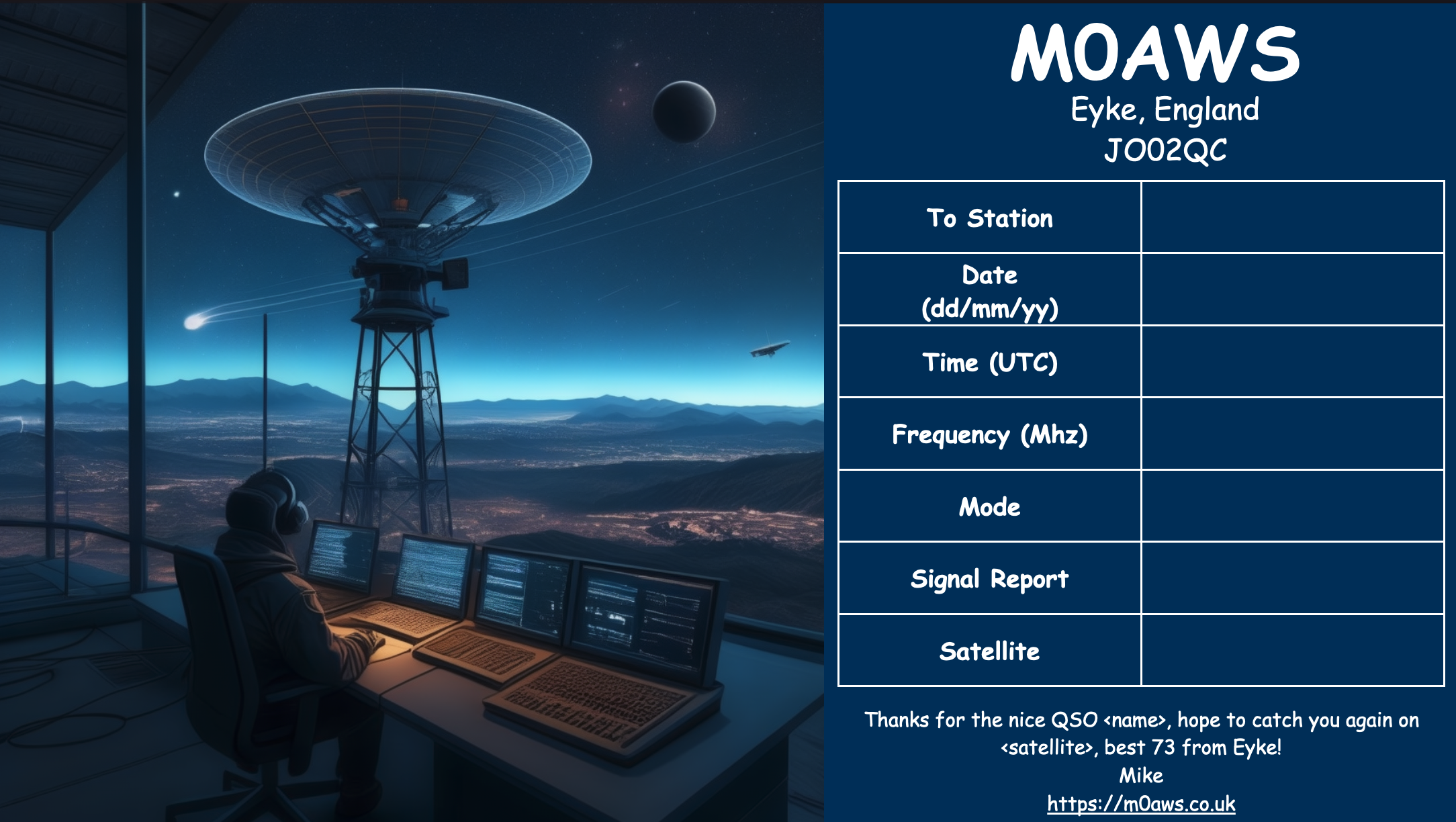
I’m really pleased with the results from my ventures into AI generated art. The next challenge is to create a QSL card for HF bands Contacts.

More soon …

Update to my NodeRed QO-100 Dashboard

Ever since my QO-100 ground station has been operational I’ve been using my NodeRed QO-100 Dashboard to control my IC-705 and GQRX SDR software to drive my NooElec SmartSDR receiver. This gives me a full duplex ground station with both transmit and receive VFO’s synchronised.

This solution has worked incredibly well from the outset and over time I’ve added extra functionality that I’ve found to be useful to enhance the overall setup.

The latest addition to the ground station solution is a Sennheiser Headset that I picked up for just £56 on Amazon (Much cheaper than the Heil equivalents at the HAM stores!) and have found it to be excellent. The audio quality from both the mic and the headphones is extremely good whilst being light and comfortable to wear for extended periods.

M0AWS - Sennheiser SC 165
M0AWS – Sennheiser SC 165 Headset

To incorporate this into the ground station the headset is connected to my Kubuntu PC and the audio chain to the IC-705 is sent wirelessly using the latest version of WFView. This works extremely well. The receive audio comes directly from the GQRX SDR software to the headphones so that I have a full duplex headset combination.

Audio routing is done via pulse audio on the Kubuntu PC and is very easy to setup.

Since I no longer have a mic connected to the IC-705 directly I found that I needed a way to operate the PTT wirelessly and this is where the latest addition to my NodeRed QO-100 Dashboard comes in.

Adding a little functionality to the NodeRed flow I was able to create a button that toggles the IC-705 PTT state on and off giving me the ability to easily switch between receive and transmit using a simple XMLRPC node without the need for a physical PTT button.

M0AWS - Additional NodeRed PTT Flow
M0AWS – Additional NodeRed PTT Flow

The PTT state and PTT button colour change is handled by the Toggle PTT function node shown in the above flow. The code to do this is relatively simple as shown below.

M0AWS - NodeRed Toggle PTT Function to change button colour
M0AWS – NodeRed Toggle PTT Function to change button colour

The entire QO-100 Dashboard flow has grown somewhat from it’s initial conception but, it provides all the functionality that I require to operate a full duplex station on the QO-100 satellite.

M0AWS - NodeRed QO-100 Dashboard complete flow
M0AWS – NodeRed QO-100 Dashboard complete flow

This simple but, effective PTT solution works great and leaves me hands free whilst talking on the satellite or the HF bands when using the IC-705. This also means that when using my IC-705 it only requires the coax to be connected, everything else is done via Wifi keeping things nice and tidy in the radio shack.

M0AWS - Updated NodeRed QO-100 Dashboard with PTT button
M0AWS – Updated NodeRed QO-100 Dashboard with PTT button

The image above shows the QO-100 ground station in receive cycle with the RX/TX VFO’s in split mode as the DX station was slightly off frequency to me. The PTT button goes red when in TX mode just like the split button shown above for visual reference.

As you can probably tell, I’m a huge fan of NodeRed and have put together quite a few projects using it, including my HF Bands Live Monitoring web page.

More soon …

Aurora!

We have an incredible view of the Aurora this evening here in Suffolk. Here’s a few photos my wife and I have taken in the last hour.

10/05/24 Aurora in Suffolk UK

More soon …

The Art of Articulation

Since I’ve been using my Icom IC-705 on the QO-100 satellite I’ve been getting no end of unsolicited great audio reports with one Op even saying I have the best audio he’s ever heard on the satellite.

Most people are surprised when I tell them that I am using the stock fist mic that comes with the radio. It’s nothing special, in fact it’s rather cheap and plastic, not particularly good quality however, it does seem to have a good sounding mic insert.

The other great thing about the IC-705 is that it has a two channel parametric equaliser built into the radio. Many people don’t realise this and miss out on the massive improvement they can make to their transmitted audio with just a few simple adjustments.

The stock fist mic has a very flat response across the audio frequency range out of the box and doesn’t sound particularly inspiring. Many see this as a negative and often just replace the mic with either a headset (probably from Heil), a boom mic (again probably from Heil) or another, better quality fist mic. All of these options cost varying amounts of money when in reality none of them are necessary.

Starting from a flat audio response is actually a good thing as it makes the equaliser adjustments more pronounced, making it easier to adjust the settings to suit your voice.

We all have different voices but, there is one thing that is pretty much the same for everyone and that’s the frequency range in which the articulation of the words and sounds we make can be found. It’s this part of the voice that is often lacking when we struggle to understand what the DX station is saying.

It’s become common place on the HAM bands these days for stations to boost the bass frequencies and reduce the mid and high frequencies with the net result of a horrible bass ringing sound and muddy mid range often making it very difficult to understand what is being said.

Having spent some considerable time watching the great videos on audio from the late Bob Heil, K9EID it’s clear that the most important frequencies to enhance are those around 2.5khz as this is where all the articulation is in the human voice.

To this end I set about setting up the audio on my IC-705 QRP radio so that my voice sounded such that it is easy to comprehend even in the most difficult of situations on air. This doesn’t mean that it has to be very harsh and overly bright, quite the opposite in that to be heard clearly in all conditions on air one’s audio needs to be balanced across the frequency range with an enhancement in the 2.5Khz frequency range.

M0AWS IC-705 Transmit audio settings - part 1
M0AWS IC-705 Transmit audio settings – part 1

To reduce the unwanted, muddy bass the first thing to do is change the transmit bandwidth for the “Wide” setting to 200-2900Hz. This will cut off the bottom 100Hz from the voice reducing the overall bass output from the standard fist mic that comes with the radio. This will ensure a 2700Hz wide SSB signal, the recommended max for QO-100 operations and the preferred bandwidth on the HF bands.

On top of this I made a further reduction of 2dB on the TX Bass setting to help balance out the overall audio response of the mic insert.

Next I set about enhancing the higher frequency response of the mic insert and found that it required an increase of 4dB to bring out the articulation of my voice. This enhanced my audio considerably compared to the standard output from the fist mic and improved the intelligibility of my voice considerably, especially in difficult band conditions.

To complete the setup I set the compression to 3 and mic gain to 35 so that the overall drive level is increased slightly giving a greater average output from the radio.

M0AWS IC-705 Audio Settings - part 2
M0AWS IC-705 Audio Settings – part 2

Once I’d got the audio setup correctly I enabled the configuration by setting the Transmit Bandwidth (TBW) to the “Wide” config in the IC-705 Function menu so that the correct settings were made active.

Ever since making these relatively easy changes I have had no end of unsolicited great audio reports from stations asking me what mic I am using and how I’ve managed to get such good audio from the IC-705. Many are surprised that I am using the OEM fist mic that comes with the radio and I’m sure there are those who don’t believe me!

Of course all voices are slightly different and these settings may not be perfect for your voice but, all those that have tried these settings have told me that their audio sounds better than ever and that DX stations often comment on how good their audio is.

I also went through the same exercise with my Yaesu FTDX10 with it’s standard fist mic and again achieved excellent results with it’s 3 channel parametric equaliser. I’ll go through the somewhat more complicated setup for the FTDX10 in another article soon.

Building HAM Clock on an old RaspberryPi

I’ve got a couple of old RaspberryPi computers on the shelf in the shack and so decided it was time for me to put one of them to good use. The first model on the shelf is the oldest and is one of the very first RaspberryPi 1 computers that was released. (It’s the one with the yellow analog video signal output on the board!). This particular model is extremely slow but, I hang onto it just as a reminder of the first SBC in the line.

The second one is a RaspberryPi 2, a quad core machine that is only slightly faster than the first model but, it’s powerful enough to run HAM Clock.

It didn’t take long to install a vanilla Raspbian Desktop O/S and get it configured on the local LAN. I installed a few packages that I like to have available on all my Linux machines and then started on the HAM Clock install.

The first thing I needed to do was install the X11 development library that is required to compile the HAM Clock binary. To do this, open a terminal and enter the command below to install the package.

sudo apt install libx11-dev

You will need to type in your password to obtain root privileges to complete the installation process and then wait for the package to be installed.

The HAM Clock source code is available from the HAM Clock Website under the Download tab in .zip format. Once downloaded unzip the file and change directory into the ESPHamClock folder ready to compile the code.

cd ~/Downloads/ESPHamClock

Once in the ESPHamClock directory you can run a command to get details on how to compile the source code.

make help

This will check your system to see what screen resolutions are available and then list out the options available to you for compiling the code as shown below.

The following targets are available (as appropriate for your system)

    hamclock-800x480          X11 GUI desktop version, AKA hamclock
    hamclock-1600x960         X11 GUI desktop version, larger, AKA hamclock-big
    hamclock-2400x1440        X11 GUI desktop version, larger yet
    hamclock-3200x1920        X11 GUI desktop version, huge

    hamclock-web-800x480      web server only (no display)
    hamclock-web-1600x960     web server only (no display), larger
    hamclock-web-2400x1440    web server only (no display), larger yet
    hamclock-web-3200x1920    web server only (no display), huge

    hamclock-fb0-800x480      RPi stand-alone /dev/fb0, AKA hamclock-fb0-small
    hamclock-fb0-1600x960     RPi stand-alone /dev/fb0, larger, AKA hamclock-fb0
    hamclock-fb0-2400x1440    RPi stand-alone /dev/fb0, larger yet
    hamclock-fb0-3200x1920    RPi stand-alone /dev/fb0, huge

For my system 1600×960 was the best option and so I compiled the code using the command as follows.

make hamclock-1600x960

It’s no surprise that it takes a while to compile the code on such a low powered device. I can’t tell you how long exactly as I went and made a brew and did a few other things whilst it was running but, it took a while!

Once the compilation was complete you then need to install the application to your desktop environment and move the binary to the correct directory.

make install

Once the install is complete there should be an icon on the GUI desktop to start the app. If like mine it didn’t create the icon then you can start the HAM Clock by using the following command in the terminal.

/usr/local/bin/hamclock &

The first time you start the app you’ll need to enter your station information, callsign, location etc and then select the settings you want to use. There are 4 pages of options for configuring the app all of which are described in the user documentation.

M0AWS - HAM Clock running on RaspberryPi Computer
M0AWS – HAM Clock running on RaspberryPi Computer

Once the configuration is complete the map will populate with the default panels and data. I tailored my panels to show the items of interest to me namely, POTA, SOTA, International Beacon Project and the ISS space station track. I was hoping to be able to display more than one satellite at a time on the map however, the interface only allows for one bird to be tracked at a time.

You can access the HAM Clock from another computer using a web browser pointed at your RaspberryPi on your local LAN using either the IP address or the hostname of the device.

http://<hostname>:8081/live.html

or

http://<ip-address>:8081/live.html

You can also control the HAM Clock remotely via web browser using a set of web commands that are detailed on port 8080 of the device.

http://<hostname or ip-address>:8080/

M0AWS - HAM Clock remote command set
M0AWS – HAM Clock remote command set

This is a great addition to any HAM shack especially if, like me you have an old HDTV on the wall of the shack that is crying out to display something useful.

More soon …

More 868Mhz Antenna Tests

After initially finding that I couldn’t tune the 868Mhz ground plane antenna with the radials bent down at 45 degrees I decided to experiment to find out why.

Initially I had the radials connected to the 4 corners of the base of the chassis mount N Type socket. This works great if you have the radials completely horizontal and gives an SWR of 1.1:1 but, with the radials bent down at 45 degrees the best SWR is around 2:1.

M0AWS 868Mhz Ground Plane Antenna Close Up

Removing the radials from the base of the N Type chassis socket and soldering them to the outer of the N Type plug at the same level as the feed point for the radiating element I found that an almost perfect SWR can be achieved very easily.

M0AWS 686Mhz Antenna with radials soldered to the N Type Plug
M0AWS 868Mhz Antenna with radials soldered to the N Type Plug

It seemed weird to me that such a small change could have such a big effect on the obtainable SWR for the antenna but, as can be seen in the image below with the radials soldered to the N Type plug and bent downwards I immediately got an SWR of 1.07:1 and a much wider SWR curve.

M0AWS 868Mhz Antenna SWR curve with radials soldered to N Type plug.

By making my own antennas I’m learning a lot about antenna design for the 800-900Mhz frequency range. Minor changes seem to have a much bigger impact than they do at much lower frequencies.

More soon …

Difference between dBi and dBd

This is a question I get asked regularly via email and so I decided to post this article so that I can refer to it in future emails.

Callum of DXCommander fame has just published a great video explaining the difference between dBi and dBd that is well worth watching if you don’t understand the difference between the two.

More soon …

868Mhz Ground Plane Vertical Antenna

In my quest to improve my Meshtastic signal range using home-brew antennas I’ve finally put together a neat little ground plane vertical antenna for the 868Mhz ISM band.

The design follows the normal ground plane simplicity using 4 radials and a vertical radiating element albeit on a tiny scale. The radiating element is 82mm long and the radials are each 92mm long.

M0AWS 868Mhz Ground Plane Vertical Antenna

Initially I modelled the antenna at a height of 3m above the ground with the radials tilted downwards at 45 degrees. I took this approach as this is how I have built ground plane verticals for the 70cm band in the past and so I thought I’d try the same approach on the 868Mhz ISM band. (I later found this to be detrimental to tuning!)

The 3D far field plot for the antenna shows it has a very nice, relatively high gain lobe at just 2 degrees elevation with a number of lower gain lobes higher up.

M0AWS 868Mhz Ground Plane Vertical Antenna 3D Far Field Plot

Looking at the 2D far field plot you can get a better understanding of the radiation pattern and gain figures at various angles. At 2 degrees there is 6.7dBi gain with the next major lobe being at 8 degrees with 4.36dBi gain, far more than I imagined I’d see for such a simple antenna.

M0AWS 868Mhz Ground Plane Vertical Antenna 2D Far Field Plot

Putting the antenna together was easy enough with particular attention being paid to the measurements of both the radials and radiating element. I soldered some lugs to the ends of the 2.5mm diameter solid core wire radials to enable easy attachment to the N Type chassis socket that I decided to use as the base for the antenna. This worked out well and provided a good solid mechanical and electrical connection for the 4 radials.

For the radiating element I used an N Type plug with the vertical 2.5mm solid core wire element soldered to the inner centre pin of the male connector. I also slid a small piece of insulation down the wire to stop it from shorting against the metal outer of the plug and then pushed in a tight rubber plug to stop water ingress.

M0AWS 868Mhz Ground Plane Antenna Close Up

Connecting my VNA I found the antenna was mostly resonant at 790Mhz with an SWR of 2.5:1. I knew this would be the case and that the wires would need a little trimming.

Trimming the wires a couple of times in 1mm nibbles I got the point of resonance up to 868Mhz but, the antenna was still exhibiting a lot of reactance that was keeping the SWR above 2:1. Trimming the radials reduced this slightly but, I could not get an SWR much lower than 1.95:1.

Scratching my head I decided to try moving the radials back up so that they were horizontal rather than at 45 degrees downwards, this had the immediate effect of the SWR dropping to 1.1:1.

M0AWS A rather fuzzy photo of the 868Mhz SWR curve for the GP Antenna

The SWR stays below 1.2:1 from 868Mhz to 871Mhz which is plenty wide enough for the Meshtastic devices. Why there is so much reactance when the radials are bent down at 45 degrees I am not sure, but it was easy enough to resolve.

M0AWS 868Mhz Ground Plane Antenna

The finished antenna is tiny but, seems to work well. Signals from my other nodes are up by 6-9dB according to the SNR reports in the Meshtastic app. I now need to make a couple more of these for my other nodes and then hope to hear some other nodes locally once they appear on air.

Remodelling the antenna in EzNEC with the radials as shown above the gain at 2 degrees is now 5.5dBi, down 1.2dBi but, the overall radiation pattern is identical to the original.

Total cost of the build is about £1 and an hour of my time tinkering with it, bargain!

M0AWS-4 Meshtastic Node 868Mhz Antenna Deployment

More soon …

Stray capacitance effects on SWR at 868Mhz

Following on from my last article on improving the Heltec ESP32 v3 antennas I found during the installation of the 90 degree SMA connector that the device was very sensitive to stray capacitance from things around it. After reconnecting my VNA I found the SWR curve would change substantially depending on what the device was near and so I set about rectifying this.

I decided to remove all the insulation from the single radial inside the unit and then added two more radials to increase the ground for the antenna to tune against. I then removed the N type plug with the antenna connected to it and made a new antenna from a piece of 1.5mm solid core insulated mains wire connected directly to the N type socket, without using an N type plug. Tuning to resonance was much easier than before and I soon had the SWR down to 1.2:1. Moving the device around and placing near to other objects the SWR curve was now much more stable than before with only very slight changes in curve shape.

M0AWS Updated 868Mhz Antenna

Making this change to the 868Mhz antenna has shown an improvement in signal strength from my node-1 device of almost +0.5dB, every dB counts when you only have 100mW to play with!

The Bluetooth antenna update has made a massive improvement to the usability of the device via the iOS Meshtastic app. Being able to have a reliable, solid connection from anywhere in the house is great and I no longer lose messages because I’ve strayed outside the range of the Bluetooth connection.

I now have 2 new Heltec ESP32 v3 devices on the way to me and will be getting those configured and operational outside with external antennas in the hope of hearing some nodes locally to me.

More soon …

Improving the antennas on Heltec ESP32 v3 Devices

The Heltec ESP32 v3 LORA devices have a coil type Bluetooth/Wifi antenna on the PCB from the factory. This antenna doesn’t work particularly well and has very limited range so, I decided to do something about it.

Getting out the calculator a quarter wave at 2400Mhz is 29.7mm. Looking at the coil antenna on the PCB I decided the best way to connect the new antenna would be to solder it to the coil of the existing antenna. This would short out the coil completely whilst creating a solid mount point for the new antenna.

After a little measuring I decided to use a 31mm long piece of 1.5mm hard core mains cable for the new antenna. I stripped back the insulation from one end of the wire so that the exposed copper wire was exactly the length to short across all the windings of the coil antenna on the PCB.

Attaching replacement Bluetooth Antenna to the Heltec ESP32 v3 Device

Attaching the the wire to the coil was easy enough to do but, it’s worth pointing out that you need to be quick so that the heat doesn’t transfer down onto the PCB desoldering the coil antenna from the device.

Whilst tinkering with the Bluetooth antenna I decided I would also make a neat little quarter wave 868Mhz vertical antenna for this device whilst I had it all apart. This is my Meshtastic node-2 and it’s sole purpose is to allow me to use my iPad to send/receive messages via bluetooth which are then forwarded on to my base node-1 in the house. Node-1 is connected to the house wifi and the Meshtastic MQTT server. This combination allows me to message people on the mesh even though there are no local nodes within RF range.

Running the numbers for the 868Mhz antenna the vertical will need to be around 82.1mm long with a radial of similar length. I had to hand a very nice SMA to N Type chassis mount socket that would be ideal to mount the antenna to the case. I drilled out the holes in the case, measured out the wires and attached it all to the case. Connecting the antenna to the N Type socket I connected my VNA and set about tuning the antenna to resonance.

M0AWS Hidden Radial for the 868Mhz Heltec Antenna

Squeezing the radial and SMA connector into the case I realised I really could do with a 90 degree SMA connector so, I quickly ordered one from Amazon which will be delivered tomorrow. Connecting up my VNA, I had to trim the antenna down to get it to resonance. The SWR ended up at 1.2:1 which is ideal. I ended up cutting off more wire than I thought I would to get the antenna to resonance but, this is due to the extra capacitance caused by the insulation on the wire. If I had used bare copper wire then I wouldn’t of had to cut so much off. I eventually ended up with around 72.9mm of wire for both the antenna and radial.

M0AWS Heltec ESP32 v3 Device with replacement Bluetooth and 868Mhz Antennas

Putting the device back into the case and connecting the USB battery the device fired up and immediately connected to my node in the house. Checking the signal strength of node-1 in the house I could see a 7dB increase in signal strength compared to the little wire antenna that comes with the device. This is a significant improvement for such a simple antenna and well worth the effort.

Next I had to drill a hole in the front of the Heltec case so that the Bluetooth antenna could poke out the front and be bent up vertically. This worked out really well and improved the Bluetooth range massively.

M0AWS Completed alterations to the Heltec ESP32 v3 antennas

Putting the node back in the house and taking my iPad down to the end of the garden some 30m away I could instantly connect to the device via Bluetooth from my iPad, something I’d not been able to do prior to adding the new antennas. I can now use the Heltec device via Bluetooth from anywhere in the house or garden making it much more accessible.

It’s amazing the difference an hour and two little pieces of wire can make to these devices and is well worth the effort.

More soon …